
The inlet pressure acts beneath the valve disc and is balanced against atmospheric pressure through a vent port located above the inlet balancing piston.
At the same time, the outlet pressure is applied above the control piston, which is designed with a predetermined area ratio relative to the valve disc. This pressure is also referenced to atmospheric pressure through the vent port.
As operating conditions change, the valve automatically adjusts its position to regulate flow and maintain a constant pressure ratio between the upstream and downstream sides (for example, 5:1). This ratio is determined by the proportional relationship between the effective areas of the valve disc and the control piston.
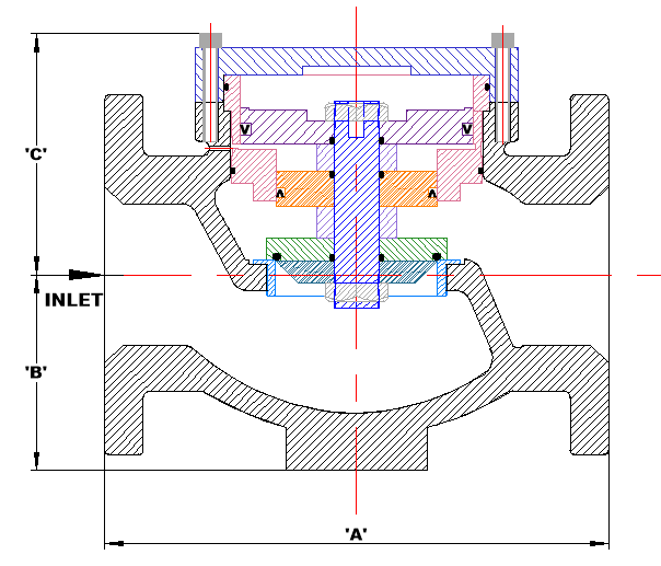
The Fig. 119 Ratio Reducing Valve is a specialized pressure-regulating valve designed to lower a high inlet pressure to a reduced outlet pressure while maintaining a fixed pressure ratio.
These valves deliver precise and dependable pressure control, ensuring that the downstream pressure remains stable, consistent, and proportional to variations in the upstream pressure.
Valve Size | 80 | 100 | 125 | 150 |
‘A’ | 292 | 356 | 356 | 445 |
‘B’ | 105 | 140 | 140 | 165 |
‘C’ | 160 | 170 | 170 | 250 |
| Material | SG Iron, Cast Steel or Stainless Steel |
|---|---|
| Connections | 25-50mm Screwed or 40-150mm Flanged |
| Working Pressure | 2600 kPa (Can be manufactured for higher pressures) |
| Ratio’s | 5:1, 4:1, 3:1, 2:1 – Custom Ratios Available |
| Temperature Range (Nitrile seals) | 0oC – 80oC |
| Temperature Range (Viton seals) | Above 80oC |
Need a customized solution? Get in touch with us today and let us know your requirements.